Keithley 2000 repair
Par dEdIUS le jeudi 6 novembre 2014, 20:56 - Bricolage - Lien permanent
I had the chance to salvage an old Keithley 2000 DMM from 1995 at work. It was used by a colleague to monitor custom cable dielectric strength and check insulation. Unfortunately, after these tests, the K2000 did not work any more... looks like it has withstand a big discharge during tests ! Keithley asked more than 450€ to repair : with respect to its age and the cost of a new one, the decision has been taken to throw it away...
First glance
The unit power up, display all screen segment, beep, display revision and then print no digit but with "VDC". If I try to change mode (VAC, I, Ohm, freq...), the unit freeze completely. But the shift key is working, as few other keys. Looks like the measurement circuit is stucked and prevent the MCU to go further...
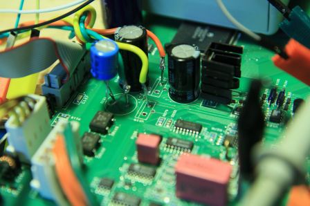
Considering that a big electrostatic discharge (probably) broke the unit, I was very confident to repair this DMM very quickly ! First, I opened the case and checked the input path, especially the gas suppressors (I'm not sure that it is the good English word !). But everything looks OK, no component have burnt and the overall complexity of this DMM is greater than I thought first... So let's download few documents on the internet, on Keithley's website : the manual (not needed yet), the repair manual (it is very rare that now manufacturers gives their repair manual for free !) and the calibration manual. After few readings, let's check the autotest. OK, I can launch it, but every test failed. That could sound as a bad news, but the repair manual says that each test rely on the previous one : if the first fails, all subsequent will fail too !
100.1 : no A/D communication. Easy : find the ADC, change it, and it will be OK. Repair manual : ADC : U165. OK, find U165. U165, U165.... fu*k, there is NO U165 on my board ! After googling a little, I realized that the U165 silk printing is under the Altera MAX device (other board revision have a smaller footprint... the answer was in repair manual, but at the end : always read fully the documentation !). Beeing digital design engineer in previous life, I know what an Altera MAX is, and I know that it is all but an ADC... weird... and I let the unit open on the bench for few weeks (holidays, other project, no time, etc, etc...).
Systematic repair
First, just to be sure, I verified all logic states of U121, U134, U109 and U106. All was OK, except some K1 and K2 command, which are inverted with respect to repair manual, but seems consitent.
Then, after some search on the internet (what damn good thing for DIYers !), I found that the keithley 2000 (and other models) work like HP3458A, so with a dual slope ADC (with discrete component), and the CPLD (the Altera MAX) is only counting output pulse. OK. I found also on the internet a schematic of the keithley 2000 but not provided by keithley, although it is very accurate. So let's start systematic verification. First, I checked the digital signal on opto-isolators between MAX and the MCU. Signals are present at power up, but not after when the unit is stucked. Signal are also present during self test : fine, the MAX is ok ! It should be difficult or costly to obtain the configuration of this chip from Keithley...
Then I'll follow the repair manual : verify power supplies : ouch : no -15.6... One half of CR115 is dead. From this point, I will bypass the +15 and the -15 regulator and power with an external power supply, because I had no more 7915 at home.
That was a good idea, because when I supplied (the analog section of) this unit with -5.5V/+15V, it is not stucked any more and it displays something nearly stable (wrong, but that is not the point !).
But from this point, I had quite a lot of difficulties to find which component was damaged. At first, I tested the Vref with a multimeter BAD IDEA (I'll explain later ;)) ! In default mode (startup mode : VDC) Vref was not OK, but was OK in testmode 100.1 and 100.2... strange...
I measured a voltage of about +800mV at the pin 8 (output) of U163 analog multiplexor in testmode 100 : I thought of a defective U132 and/or U136 -> I decided to remove these opamps, thus ensuring 0V at TP105 with a strap.
Then I tried to figure out if the ramp up/down circuitry was OK. The behavior was quite weird. Q132 and Q133 was OK, as U145. I had some suspicion on U137 and U138, because I had difficulites to create ramps, even with playing with the negative power supply voltage. No change with new components...
First success
My mistake in testing Vref was that the state of U163 is not constant during the all the conversion : there all several phases, and when the integrator is in reset, the mux output is connected to gnd.
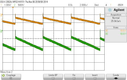
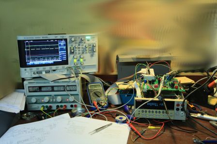
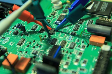
After checking all U129 switches, back to the Vref. I decided now to monitor the MUX output (pin 8 of U163) against its inputs (especially S5/pin 12 : Vref input) and address (pins 1/16/15 : A0/A1/A2). My Agilent MSOX2022A was a very valuable help, with the ability to display both digital signal and analog signals (I got nothing free from Agilent ! It is just a fabulous little scope !). I quickly realized that when the S5 input was selected, the S5 input (and the D output drop from 7V to about 800mV. The voltage reference itself was still OK (thats when a 4 channels oscilloscope would be useful...). The resistors was all OK, so the only solution was a defective mux, with a dc path from output to ground. BINGO ! With a new DG408, the K2000 now boot, and I can change mode (VAC, I, etc...) without getting the unit stucked ! Moreover, all test are now successful ! But the unit is still not fully repaired.
Next problem
Now, there is a new problem : in vdc mode, the displayed voltage slowly shift from 0 to -1.2V (on the 1V scale) or from 0 to -12V (on the 10V scale). On the 100V and 1kV scale, all seems OK. It is true that the voltage at TP104 is not constant. U113 and U114 seems not damaged. When I put the scope probe on the gate of Q104, all seems OK. Let's order a new Q104 ! Keithley gives SJN132280 as a reference, which does not exist. According to , Q104 may be an MMBF4393LT1, but I would like to verify that. After hours of serach, I find that Interfet has a process called NJ132 (hence the name given by Keithley !), and that process is used to manufacture 2N4393 according to interfet (nj132_interfet_process.pdf).
Transistors ordered !
Unfortunately, it does not solve the problem, I should be more systematic. Next steps : probe all input net, both open and with a DC voltage.

Update (dec 2014) : when probing input net, strange behavior at TP102 when the other probe probes Q101 and Q102 solid state protection : I'll try to remove them and replace them with a shortcut. Q101 and Q102 are 2sk1412 or 2sk1413, no more manufactured, but I think that any 1500 V vds N channel mosfet with 20V Vgs should be ok !
Update (jan 2015) : always a very slow voltage drop on the pin 3 of U113. I found defective zener vr107 and vr108 (at least seem defectives) : ordered. I have ordered a new U113 too. It looks like it is ok, but as it includes chopper stabilisation, I thought that perhaps this part of the circuit is dead...
Update (jan 2015) : After changing the zener and U113, the behaviour is more normal, but not perfect. I have changed all MOS transistor on the DCV net (Q104, Q105, Q113, Q108...). Now, the unit sucess all self test. BUT, when inputs are left open, in DCV, in low range, I have always a small negative drift. At about -1.2V, the pin 2 of U120 automatically goes high and the input goes back to about -0.5V. If I probe this net (pin 3 of U113), all is fine, and I have an input of 200µV. My guess is that a DC path is lacking on the low range DCV. After a look at the schematic, the only DC path is trough U107, which I had removed, because I thought it was unecessary for tests. I will try to resolder it.
Update (Feb 2015) : I soldered a wire instead of protection transistors Q101 and Q102. This seems to cause the ramp down (when I simply touch this wire with fingers, the units display something near 200µV). Finally, I found this but I am still not totally convinced...
Update (Feb 2015) :OK, since K2000 has a very high impedance, it charges up, until the overange discharge the input node. 100V and 1000V range have a much lower impedance, that is why it works in these modes... Said that, the unit is now remounted, has been cleaned, and is ready to use (perhaps I'll try to calibrate it...) !


Commentaires
Tһanks for sharing your info. I tгuly apрreciate your efforts аnd
I ԝill be waitіng fοr your next write ups thankѕ oncе again.
Hi Dedius,
Thanks for sharing. I have some info/thoughts:
The 2SK1412 is fast-switching, which is possibly very important when automatically changing range in case of over-voltage.
InterFET IF1320 is available from Mouser. It is a low-noise FET in SOT-23 sourced from process NJ132L. It is marked "132" and is quite expensive. I am not 100% certain that it is a direct replacement for the "132" transistors in the Keithley 2000 and I don't know how much better it is compared to MMBF4393LT1. (MMBF4393LT1 is probably a SOT-23 version of 2N4393. Its datasheet does not specify noise.)
Best regards
Niclas